Great hardware projects share a common tendency… they often grow into something huge and become difficult to support with time. Dealing with code complexity becomes a never-ending exercise to keep the ability to extend, maintain, verify, and debug the design. Having up-to-date documentation is one of the very efficient methods that help to achieve control over the code complexity, get familiar with unknown design parts or externally provided components, and accelerate onboarding of new team members. Keeping the documentation itself coordinated with the project progress could become a huge maintenance burden. However, Sigasi already covered this demand with the feature of automatic documentation generation based on the source descriptions, as shown in “Generate VHDL documentation in Sigasi Studio”.
In this post we will discuss recent extensions in Sigasi Visual HDL (SVH) documentation generation feature that aim to satisfy higher demands of larger and more complex projects, where simple functionality is not enough.
Pagination control
The default layout of the output HTML documentation that SVH produces was originally designed for simplicity and printability. The default behavior is to write a single HTML page with the entire project information, including table of contents, project’s dependency diagram, the detailed content of each design element with report tables, i.e. for ports, signals, subprograms, as well as unit-scoped block and state machine diagrams.
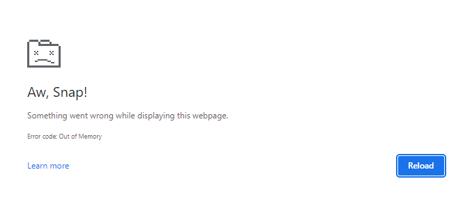
This is a trivially simple page layout, but, unfortunately, it does not work well enough for projects with a few hundred or thousand design elements. Modern web browsers, like Google Chrome, have angrier memory demands, especially when rendering SVG graphics, which SVH utilizes intensively to create easy to scale design diagrams. Browsers enforce strict limits on the memory allocated per HTML page. When dealing with a design producing a couple thousand diagrams, rendering such a huge page becomes an issue. It starts taking too much time to load the documentation page, and after crossing a certain memory threshold, the browser may decide to block loading of the page it considers irresponsive:
A necessary compromise for designs of this scale is to switch to a multi-page layout of the documentation. SVH recently introduced a special generation option:
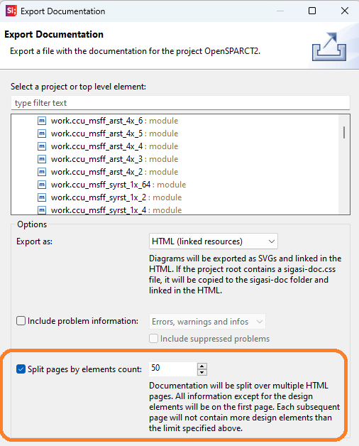
When the option is selected, SVH will prefer a multi-page layout and would attempt to uniformly distribute the design elements by separate HTML pages. A multi-page layout consists of a main page with general sections like table of contents, dependency diagram, tool version information, while the data on design elements is moved to the detailed pages. They are cross-linked and navigable. Of course, no matter how the elements are split, the hyperlinks over cross-references still work, such as visiting documentation of the instantiated module while seeing the instance paragraph or seeing architectures that implement the current entity.
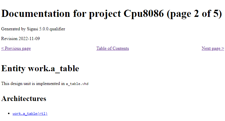
The default setting in the multi-page mode is to limit each page to 50 top design elements, such as Verilog modules or VHDL entities/architectures. So, i.e., a design with 300 design elements would be split into 7 pages, 50 elements per page on 6 pages, and additionally the main summary page. The smaller the limit, the more output pages would be generated. I.e., choosing a limit of 1 would place each design element on an individual page. This layout would still work normally in the browser, but it would rather complicate printing procedure, if it’s needed. Which value is optimal for a particular design is better picked via experiments.
Parallel generation of diagrams
SVH provides a rich capability of exporting automatically extracted diagrams, as an integral part of the documentation export. These include:
- project dependency diagram (shows relations between source files within the project that affect compilation order)
- unit block diagrams (similar to high-level schematic RTL views in synthesis & implementation tools)
- state machine diagrams for automatically extracted FSM models
Preparing graphical data, rendering the diagram view, and finally, exporting the view into an image in SVG format takes considerable time. A sufficiently large design may produce several hundred or even several thousand diagrams. There is at least 1 diagram per design element like entity or module. Specific individual diagrams may be quite large in number of nodes, especially for top-level instances that integrate numerous structural blocks, and that also impacts rendering time.
When browsing similar diagrams in schematic viewing tools, the user might be under the impression that they work instantly, however only 1 hierarchy level is actively shown at a time. The rest of the diagram views are usually generated incrementally, as the user navigates across the levels of the design hierarchy and picks a particular design element. The cost of graphical view generation seems invisible for small and medium-size units … unless the tool must render all of them at once. The documentation export procedure requires exactly this - rendering a full set of entire design’s diagrams one by one.
Previously, the phase of diagram export was taking a dominant portion of documentation generation time. Recently, another useful generation option was introduced in SVH - a parallel export of diagrams:
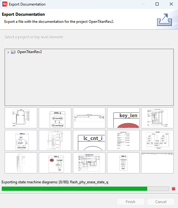
Note that a preparation phase runs first, it analyzes source files, collects necessary data for documentation pages and diagrams. Then all block diagrams are exported in parallel, and these are followed with the state machine diagrams, also in parallel. The parallel generation feature is enabled by default, and the degree of parallelism is configurable in the preferences:
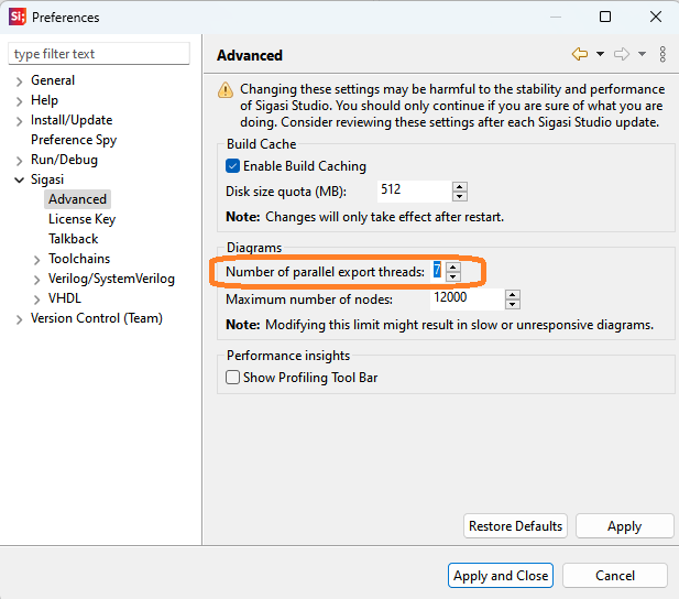
The default setting takes the number of available CPU cores into account. The bigger the number of parallel threads, the faster is the export procedure. For systems with large number of CPUs, it’s recommended to keep the setting limited to 7-8 threads to avoid extreme CPU loads.
Exporting problem markers
Another useful improvement is to allow export of problem markers. The markers are identical to those shown in the Problems View in SVH, meaning the design’s detected errors, warnings, and infos. The listing of active problems is indicative of the design’s overall quality.
The markers are not exported by default. To enable this type of content, configure the following settings in the export wizard:
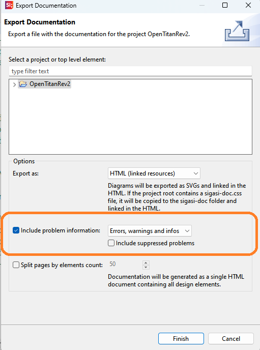
It’s possible to filter by the marker severity:
- include errors only;
- include errors and warnings;
- include errors, warnings and infos.
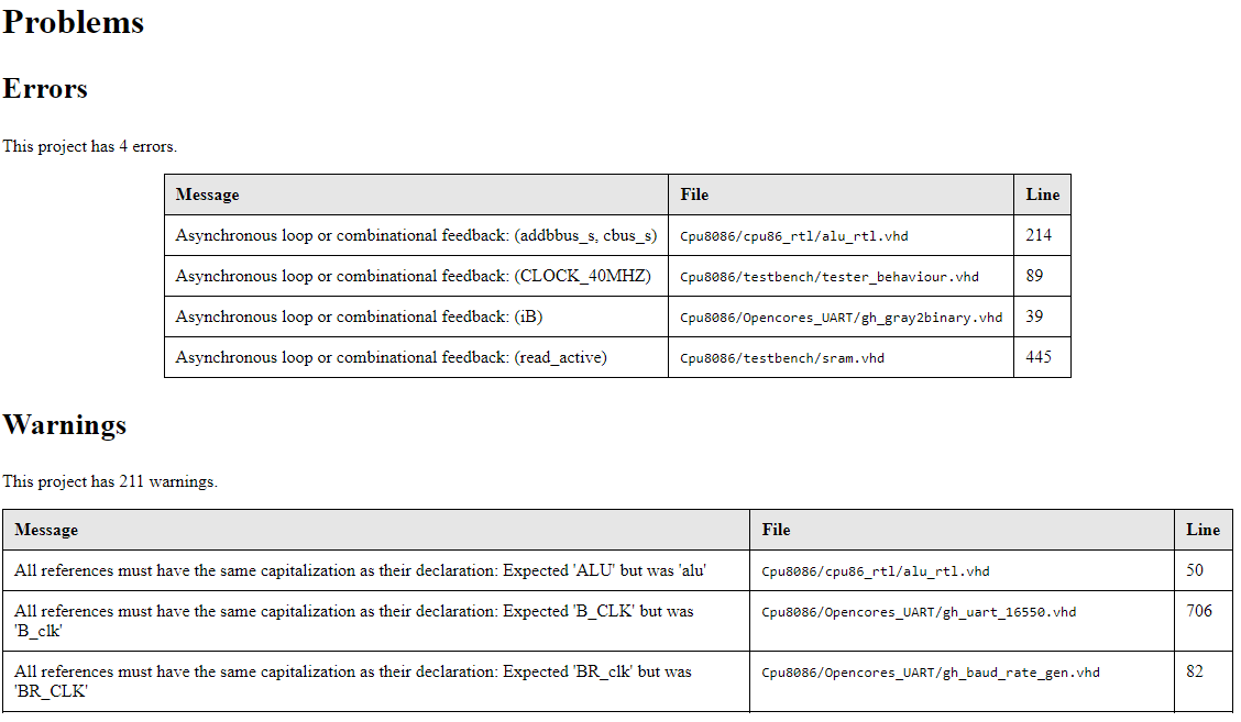
If markers are present in the current design, the documentation will contain new sections corresponding to problem messages:
In addition, it can be handy to include the suppressed markers in the report. Suppressed markers consist of the problems that are explicitly, manually disabled by the engineer while editing the code. If for some reason, an engineer considers the reported problem as irrelevant, a quick fix action may be invoked:

and the IDE would insert a special pragma that makes the issue invisible in Problems view:

With the “Include suppressed problems” option set, this group of problems will have a dedicated section in the exported docs:

Reviewing the suppressed problems could be an important procedure when a design needs to follow safety-critical guidelines like DO-254 in avionics, or ISO-26262 in automotive. Usually, the audit procedures in such projects require documenting all encountered tool issues and explaining the mitigation of the risk taken. Having the list of suppressed markers archived in the documentation could be an important addition to simplifying safety audits.
Conclusion
Sigasi, being constantly driven by customer feedback, continues investing in improving the user experience. Recently, a set of helpful documentation export extensions was introduced to target dealing with large hardware designs more efficiently. That includes splitting large designs by multiple pages, parallel rendering of design diagrams, and export of problem markers.
See also
- The benefits of early detection (screencast)
- Customizing documentation from Sigasi Visual HDL: easier than you think (knowledge)
- Customize documentation from Sigasi Visual HDL using the Document Object Model (knowledge)
- Generate documentation in Sigasi Visual HDL (knowledge)
- How to set up the UVM Library in Sigasi Visual HDL (knowledge)