The Graphics Configuration feature has been deprecated since Sigasi Studio 4.16 and was removed in Sigasi Studio 5.3.
When creating hardware designs, graphical diagrams are a huge help in comprehending complex designs more easily. Diagrams are also convenient to share with others, for example as part of technical documentation.
With the rise of hardware description languages such as VHDL, Verilog and SystemVerilog, the focus has been shifted away from graphical design to a more textual approach. The desire to display designs in diagrams has remained though, so a solution was needed to bring back diagrams to HDL based designs.
Graphical editors
One way to solve this is by providing a graphical editor that allows for designs to be drawn as diagrams. These diagrams will then generate HDL code, which can then be passed down to a compiler to verify if the design is valid. Any issues can then be reported back to the editor.

Graphical views
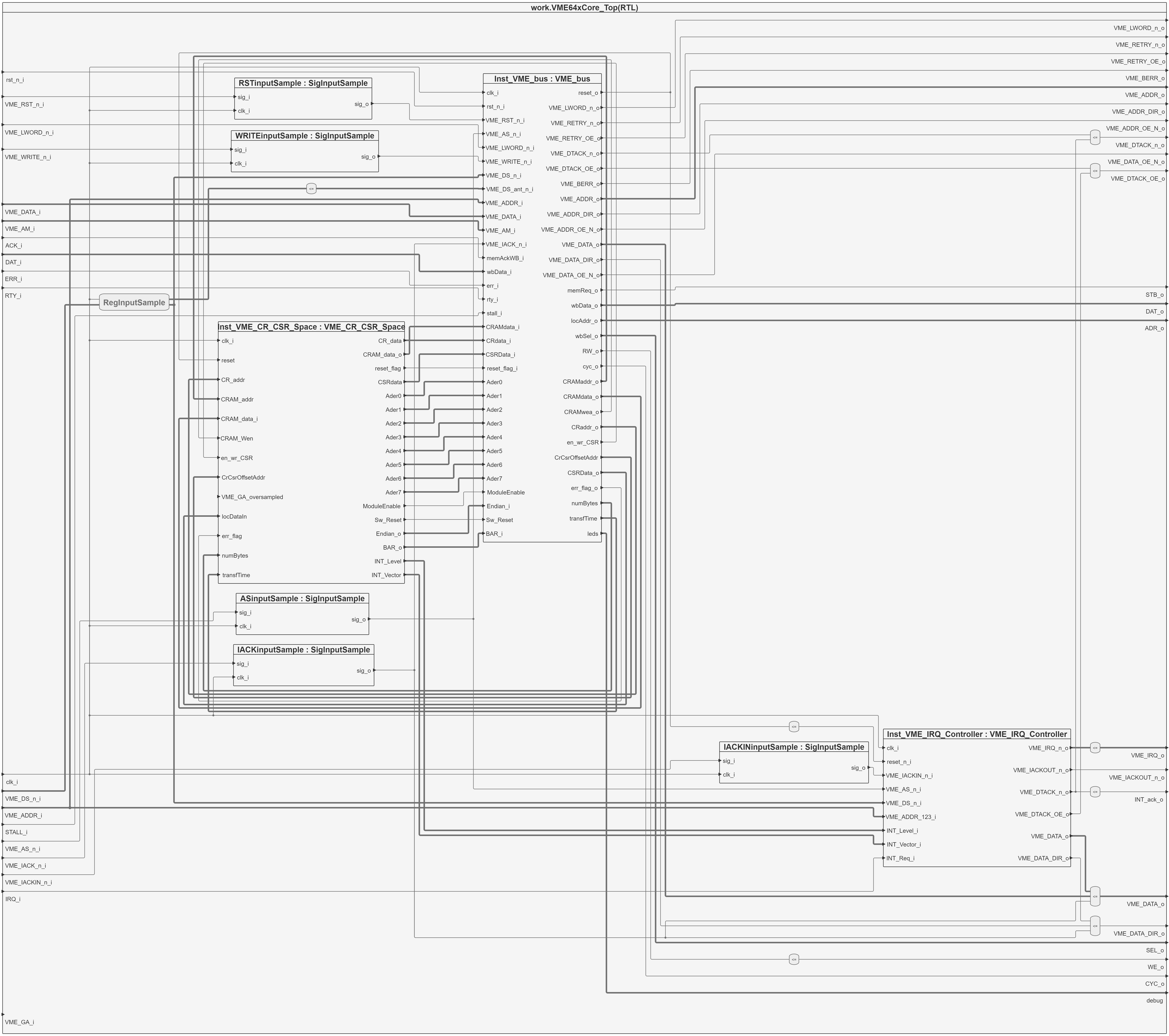
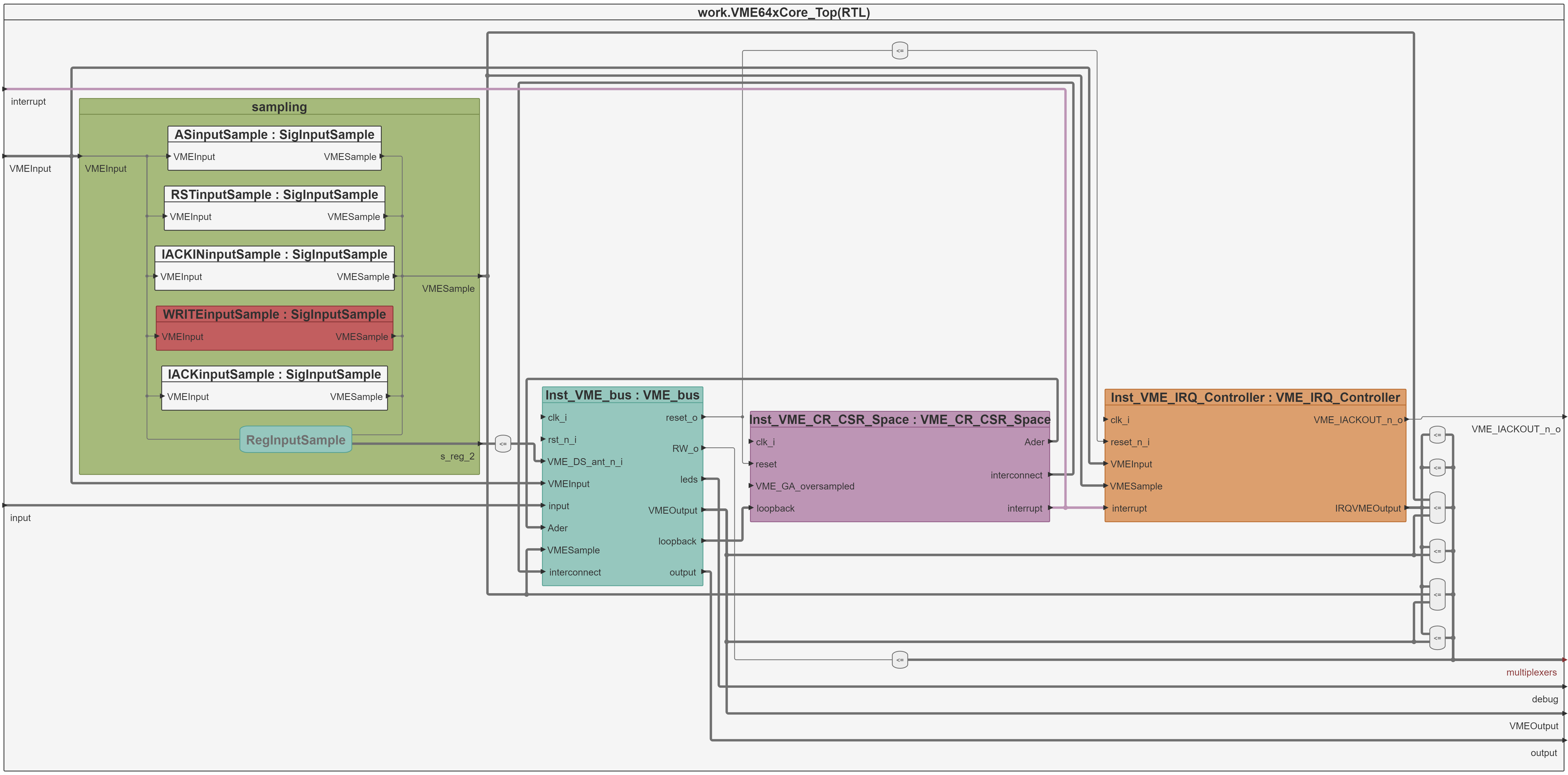
Another way to provide the benefits of graphical diagrams while putting the main focus on the HDL code, is by providing graphical views. These views can show diagrams which are generated based on HDL code, and will be updated whenever changes are made to the code. It is also possible to navigate to parts of the code from the graphical view.

Downsides to graphical editors
If we compare graphical editors that generate code to code editors that can generate diagrams more in depth, there are some downsides that one should consider.
Problem reporting
When using graphical editors, HDL code will be generated based on the diagrams drawn. To make sure that the design is valid, that generated code needs to be passed to a compiler. Whenever there are problems in the design, the compiler will respond with issues for the user to fix. These issues however are based on the generated code, not the diagram. In order to display these issues, there is some kind of translation needed to show these problems in the diagram. Otherwise one would have to explore the generated code, to try and figure out the problem, which defeats the purpose of a graphical editor.
Navigation
Nagivation from graphics to code and vice-versa can be a very powerful tool. Especially when debugging, the ability to navigate from one part in the code to the diagram element it corresponds to is extremely useful. While graphical views mostly supported this, it is not possible in graphical editors and makes tracking down and fixing issues quite the challenge.
Persistence
Another downside of graphical editors is the way diagrams are saved in between sessions. In most cases diagrams are saved in an XMI format , which contains all diagram elements, positions and links between those elements. The problem here is that the slightest change will likely result in a completely different save file, making comparison between versions almost impossible. The contents of these files are also not human-readable, so comparing them will be annoying at best. Apart from that there is no standard for storing graphical data in XMI, which makes switching to a different editor practically impossible unless you want to start from scratch.
If we were to use the generated code instead of an XMI format to save our design, we have the same problem since a simple change might drastically change the generated code. Additionally, we would have to encode positional data into the generated code to be able to redraw the original diagram.
Collaboration
With teams getting bigger, chances are two or more people will be working on the same design at the same time. For this reason using some kind of version control system is crucial to track changes over time, and help to resolve collisions when they inevitably occur. Because of the incomprehensible binary formats, fragile generated code and positional data, graphical editors struggle on this front. Handwritten HDL code on the other hand is very easy to compare.
Scale
When working on large designs, we see that diagrams will hardly scale accordingly. When diagrams get really big, they lose their benefit of providing a clear overview of a design. This is less of an issue when writing code, since you can more easily split a design into multiple files. The way the code is written and documented can also aid with understanding the design, whereas reading generated code won’t really tell you much.

Generating a diagram from code might in some cases still result in huge diagrams, however with the help of concise configuration you can easily create multiple views of the same code, without changing the actual design.

Conclusion
In our opinion the use of graphical editors that generate code have too many drawbacks when compared to using a good code editor that can generate diagrams on the fly. Keeping the focus on the code will not only help with tracking down issues faster, but will also make collaboration more feasible. We believe graphical views are best used as an aid to write better code, not hide it. This is why Sigasi Studio supports various different graphical views, such as the Block Diagrams, State Machines and Dependencies views.
See also
- The benefits of early detection (webinars)
- Japanese, Korean and Chinese comments in HDL code (screencast)
- Using Sigasi Studio's Graphics Configuration (legacy)
- Sigasi Studio Editing Tricks (legacy)
- Sigasi Studio Graphics Configuration Grammar (legacy)